The research objective is to explore the scientific bases and technologies for fabricating precision metal micro-features through micro- sheet metal forming process. This research is motivated by increasing demand for low-cost, high-precision metallic components to satisfy the requirements of efficiency, strength, temperature and/or corrosion resistance in the areas of electronics, medical devices, energy generation and heat exchangers, etc. In order to gain a deeper understanding of the micro-stamping process, the mechanics of micro- sheet metal forming processes are studied analytically, experimentally, and by using finite element simulations. The results of this research will develop more accurate material and process models for micro-stamping operations, resulting in less variation and higher yields in micro-manufacturing applications.
Characterizing the Mechanical Properties of Microscale Materials
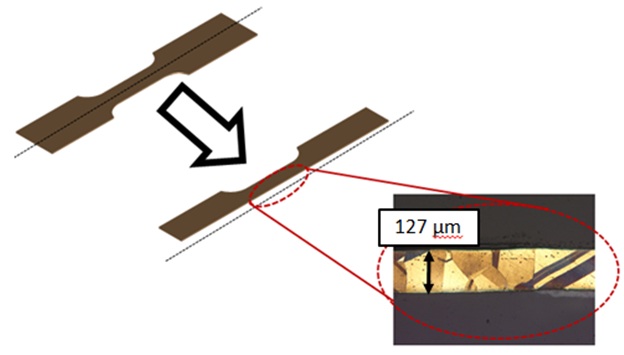
In micro-forming processes, the scale of component geometry often approaches that of the material grain size. This leads to changing mechanical behavior of materials at the microscale. This issue of 'size effects' is investigated in the micro-stamping process. For example, 127 um thick tensile specimens were heat treated to achieve 1-2 grains through the specimen thickness. It was found through micro-tensile tests that the mechanical behavior of large-grained specimens differs drastically from polycrystalline specimens of the same material. This has important implications on the mechanics of the micro-stamping process, and micro-stamping machine design.
Heat-treatment of 260 series brass results in 1-2 grains through the thickness of the material
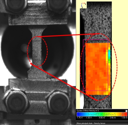
Because the scale of the materials under investigation is very small (geometric features less than 200 um), it is not always practical to use conventional sensing methods to measure material deformation (such as strain gages). Rather, non-contact methods are used to measure the strain of micro-scale materials. For our mechanical tests, a high-resolution CCD camera and digital image correlation software is used to capture images of material deformation and the software post-processes 2D strain fields in real-time.
A high-resolution CCD camera and digital image correlation software can be used as a non-contact strain measurement technique (captured image on left, computed strain field on right)
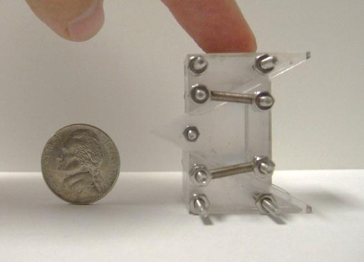
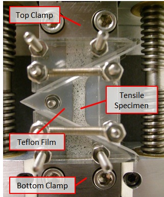
Because sheet metal components often experience prestraining and compressive loading in actual forming processes, it is important to understand the reverse loading characteristics of materials in addition to their tensile properties. A novel, transparent micro-wedge device was designed and fabricated to allow the tension and compression testing of micro-scale sheet metal specimens. The device prevents out-of-plane buckling of micro-specimens under compressive loads.
Image of Micro-wedge Device for Tension/Compression Testing of Thin Sheet Metals
Development and Validation of Micro-bending Machine
In order to study the fundamental mechanics of a representative microstamping process, a micro-bending machine was designed, fabricated, and simulated using finite-element software in order to produce precision, micro-sized formed features on metallic specimens.
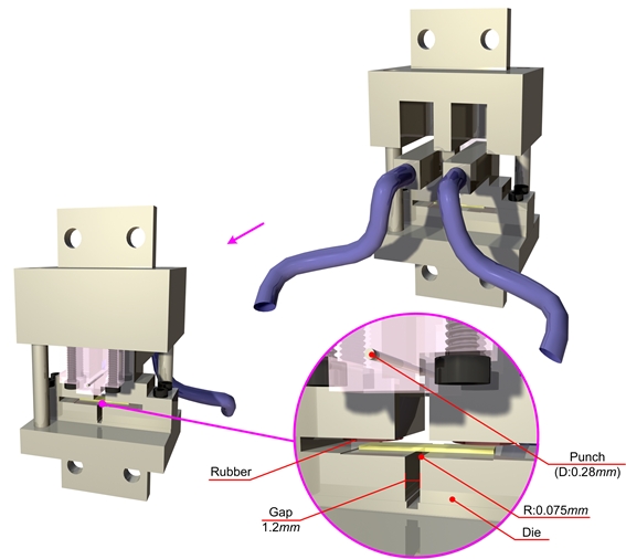
The table-top, micro-bending machine was designed such that micro-sized metallic specimens (thicknesses less than 200 μm) could be formed to high-aspect ratio geometries using steel punch of 280 μm radius. In order to fix thin sheet specimens and enable deep-drawing capabilities during the bending operation, a variable, air-pressure driven blank-holder system was employed. High-precision alignment was designed into the system by combining high-accuracy machined components with built-in alignment structures. Additionally, in-process monitoring of various measurements are recorded throughout the bending process such as bending force using a high-precision load sensor, punch displacement using a linear displacement sensor, and two-dimensional bending profile of the sheet using a high-resolution CCD camera. Imaging was realized by designing a transparent window/punch-support part into the machine; this component provided mechanical support to one end of the bending punch as well as provided a view for imaging of the bent specimen.
Diagram of Micro-bending Machine
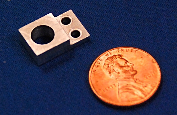
Size Comparison of Micro-bending Die and US Penny
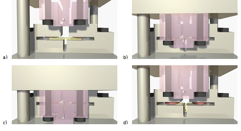
Process Simulation of Micro-bending Process:
a) mount sheet blank,
b) apply blank holder and actuate punch,
c) perform micro-bend/measure forces,
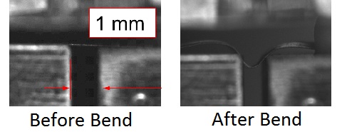
d) retract punch/observe sheet springback/remove specimenAn example of a micro-bending process for 38 μm thick Stainless Steel 316L sheet metal is shown below. Images of the steel sheet specimen, before and after bending, display visible elastic springback after micro-bending experiments.
Image of Sheet Springback for Stainless Steel 316L
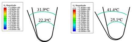
Micro-bending simulation of sheet metal bending for 127 um thick stainless steel (left) and titanium (right)
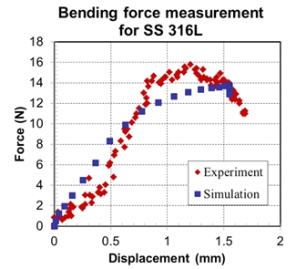
Furthermore, the measured bending force during micro-bending was compared to results from FE simulations. FE results of the bending forces match the experimental measurements very well, signifying the importance of implementing accurate material behavior in the analytical model of the micro-bending process. Future work will be conducted in order to improve the geometric accuracy of micro-formed components by taking into account more complex loading paths during bending as well as elastic springback compensation methods of micro-sized materials.
Comparison of Experimental and Simulated
Vertical Bending Force for Stainless Steel Sheet