Background
Currently, Single Point Incremental Forming (SPIF) is used to create three dimensional structures of metal sheet. The residual stresses and formability of sheet metal and machined plate are different due to the process of creation (rolling vs. machining). Deformation machining is a hybrid process combining SPIF with thin wall and thin floor machining.
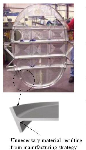
The outer edges of this aircraft part must match with the contour of the fuselage of the aircraft and therefore create acute angles with other surfaces
Although 90% of this part could be created with a 3-axis CNC machine, the entire part must be manufactured on a 5-axis CNC machine to create these angles
The proposed deformation machining process may allow for this part to be manufactured on a 3-axis machine
Cost savings are estimated to be in billions of dollars for the aircraft industry alone
A much broader impact is the new ability to create structures not previously possible
Experimental Verification
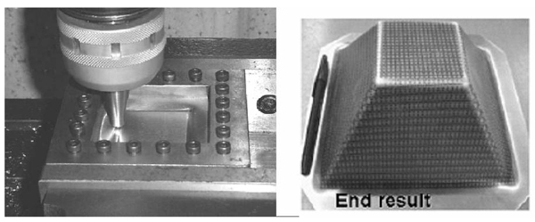
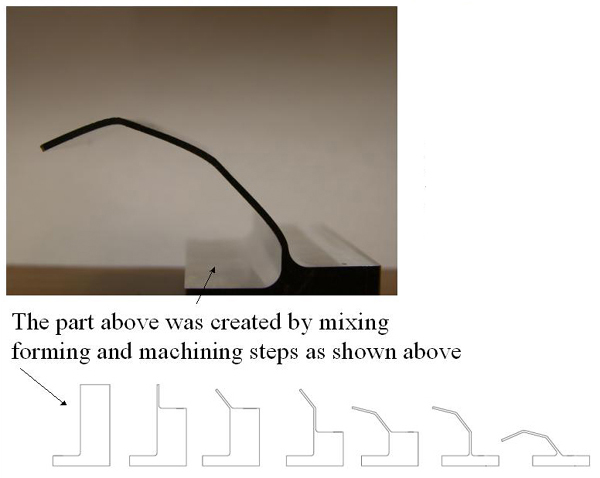
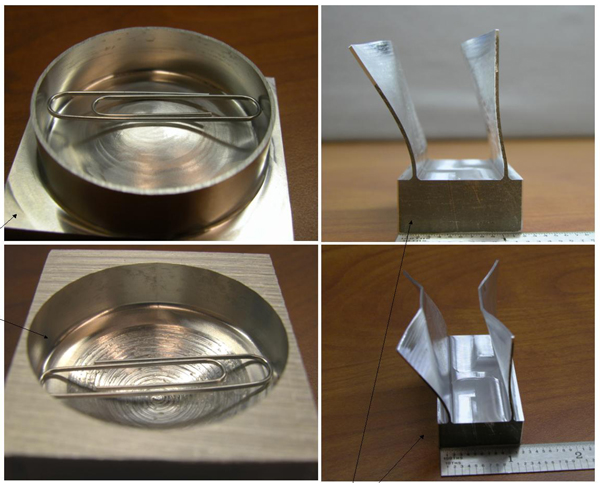
In the figure above, the part to the left was created by deforming a thin floor in a pocket. This represents a shape that is difficult to produce using standard milling techniques. The right part shows the ability to perform many intermittent machining and forming operations on a single part.
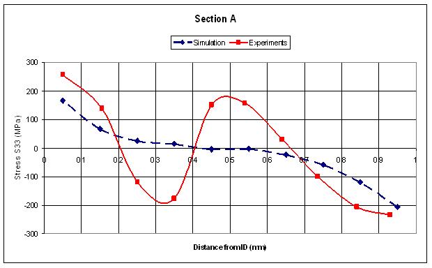
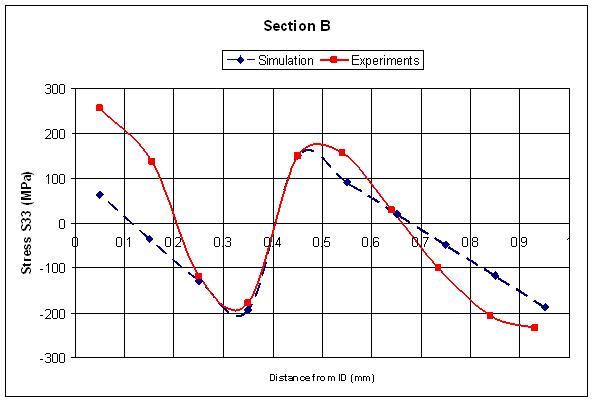
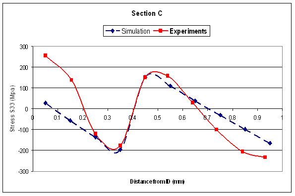
Simulation of deformation machining of thin wall (isotropic in plane of the wall, anisotropic in the thickness direction) performed with ABAQUS implicit with 10 elements in the thickness direction. The residual stresses predicted by FEA were compared with stresses measured on the actual formed component using a XRD.


Observations
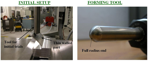
Using a tool with a full radius end helps to dramatically reduce the forming tool marks left on the surface of the part.
In all of these trials, the tool has been free to rotate however controlled rotation and lubrication need to be explored.
To create a straight wall, a curved tool path must be used to apply more force to the corners of the wall.
Using a tool path that follows the top of the wall during bending is preferrred over moving straight into the part at a constant depth.
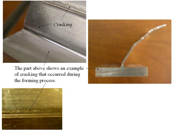
Parts with two bends can be produced without cracking if the forming tool for the second bend applies a force above the first bend.
If a vice is used to secure the workpiece, all forming must take place parallel to the clamping force.
Research Objectives
To explore feasible process planning of machining and forming for several candidate geometries
To test and preliminary model bendability and sheet formability subjected to machining;
To establish the scientific groundwork, i.e., detail fundamental challenges in this hybrid process, and
To investigate the need for rapid in-process metrology to aid in springback compensation
Questions to be answered
Should the spindle be on, free to rotate, or fixed?
How does the spindle speed and feed rate change the formability of the material?
Should the forming tool be lubricated?
How does springback affect the forming tool path and the accuracy of the path?
Can the springback be predicted accurately enough so that a proper forming tool path can be selected a priori?
What is the ultimate limit for material formability and bendability under machining and incremental forming
Project Plan
Collaborators's specialties
UNC-Challotte: Dr. Bethany Woody (PI), Dr. Scott Smith (Co-PI), David Adams
Will lead the effort in experimental verification and tool path and process parameters
University of Florida: Dr. John Ziegert
Will focus on rapid real-time metrology issues and process parameter development
Northwestern University: Dr. Jian Cao
Will lead the effort in formability/bendability analysis
ALCOA: Dr. Ming Li, Dr. Mark Newborn
Will provide material and technical advice
First Steps
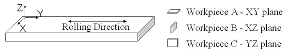
To determine what are the formability limits of machined aluminum plate (AL 7050 and/or AL 6061 both T7451). Twelve pieces (from different orienations shown below) will be made at the UF and UNC Charlotte. These test pieces will then be sent to Northwestern University where forming limit diagrams will be created. Four process parameter will be noted for each test piece.In this project, we will first demonstrate the feasibility of this concept and then lay out the scientific ground work for further development. Initially, we will experiment with varying process parameters in an attempt to understand the deformation machining process.
Test specimens orientation with respect to the grain (rolling direction)
Test specimens position within the plate
Cutting conditions
Surface finish
Overall Goals
To develop a strategy for deformation machining by integrating experimental and computational methods
To provide a design tool to aid the user in determining what features are candidates for this new process
Sponsor:
National Science Foundation