Goals
To improve the fatigue life, edge sharpness retention and hardness of a variety of dental surgical tools by the process of laser shock peening.
Challenges
Dental surgical tools are often made of surgical grade hardened 400-series steels, the high hardness reduces the effectiveness of shot peening processes.
The free-form geometries of these tools such as dental scalers, bring challenges to surface operations such as shot peening and laser shock peening (LSP).
Traditional LSP process involves using a protective bi-layer of thin metal foil and vacuum grease in order to protect the workpiece from direct laser ablation. In the case of medical instruments, however, contamination is an issue
Research Work
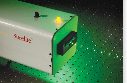
The research aims at developing a LSP process using a high energy nanosecond laser (Continuum Surelite EX) at 1064/532 nm wavelength (Fig. 1).
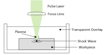
The laser provides a flat-top beam profile. A modified LSP process has been established which is free from the use of a protective (ablative) layer and utilizes a tightly focused 1064/532 nm pulsed laser beam, of 8 ns pulse duration, with a pulse energy of 0.5 J, to create a localized plasma near the surface of the workpiece immersed in distilled water (Fig. 2).The water acts as a confinement to propagate the pressure (shock) wave generated from the plasma, into the workpiece. The shock wave assists in the peening process, resulting in strain-hardening near the surface. The optimum set of processing conditions which leads to the maximum compressive residual stresses at the material surface will be determined. The residual stresses are characterized by the X-ray diffraction technique.
|
Fig. 1 - Continuum Surelite EX laser: 532 nm 8 ns |
|
|
|
Fig 2. Schematic of LSP without protective layer process |
|
|
|
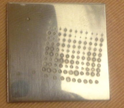
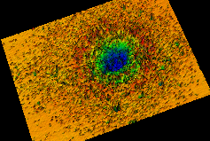
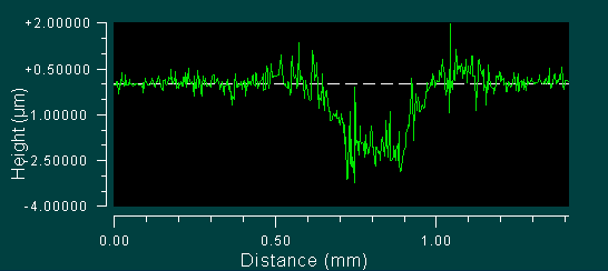
Fig. 3. (a) Shock peened spots on a 304L steel substrate; (b) Microscope image of a single crater; (c) Cross-section profile of the crater |
|
 |
|
|
(a) |
|
 |
 |
|
(b) |
(c) |