LS-DYNA® MAT_COMPRF (MAT_293): A non-orthogonal material model of woven composites in the preforming process
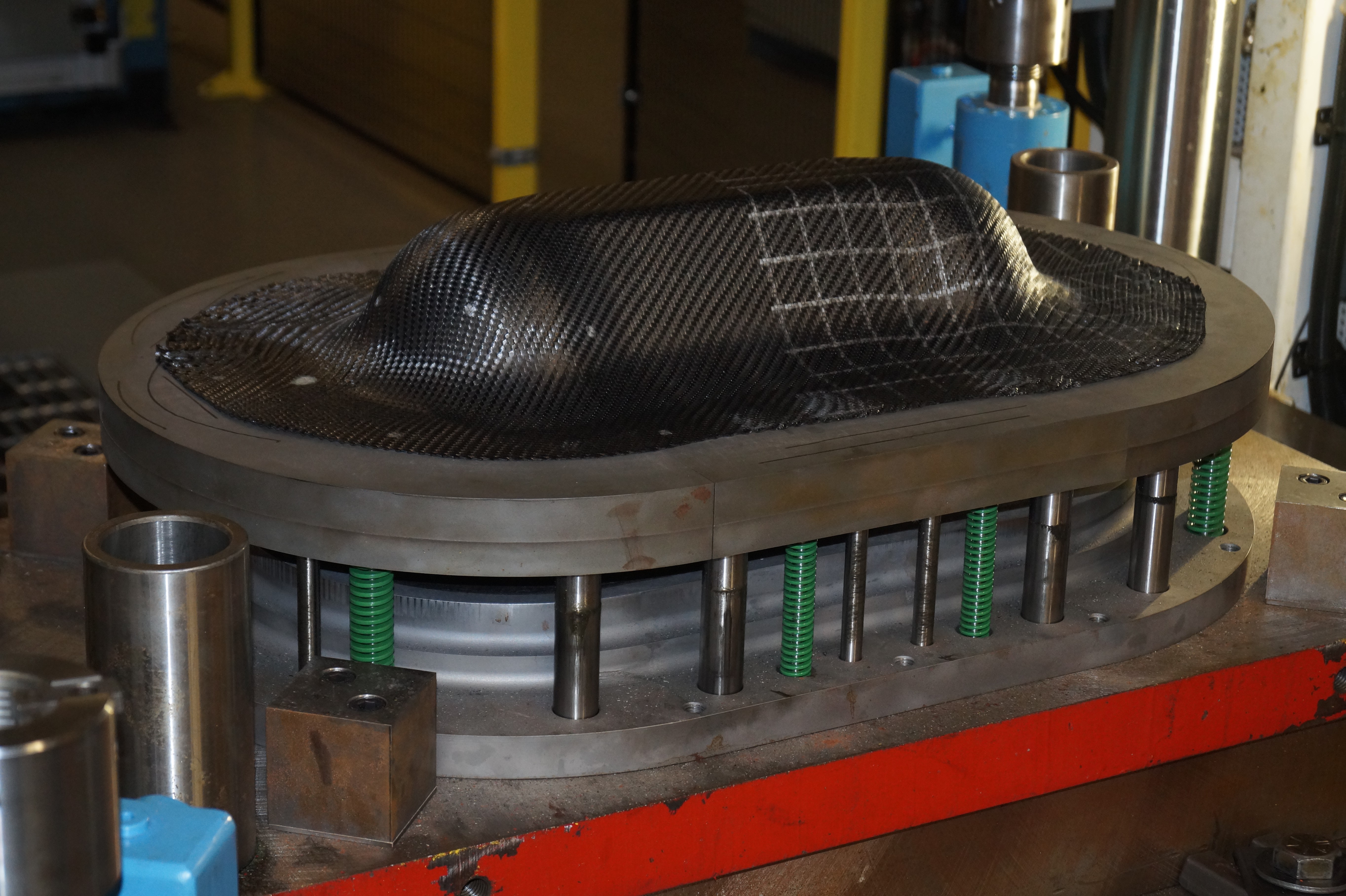
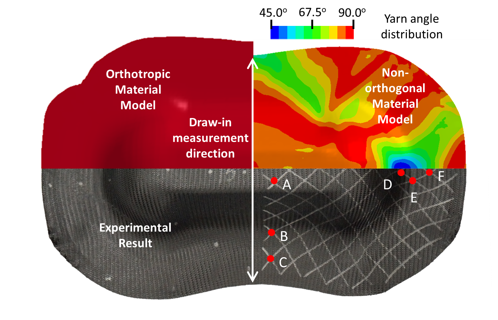
(a) Preforming experiment. (b) Comparison between traditional orthotropic, non-orthogonal MAT_COMPRF simulation and experiment results.
(a)
(b)
Introduction
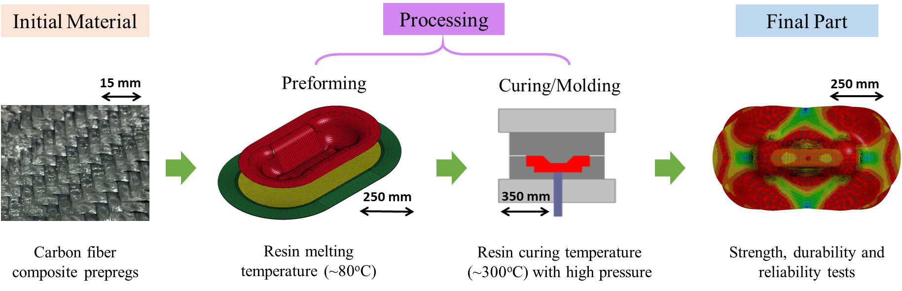
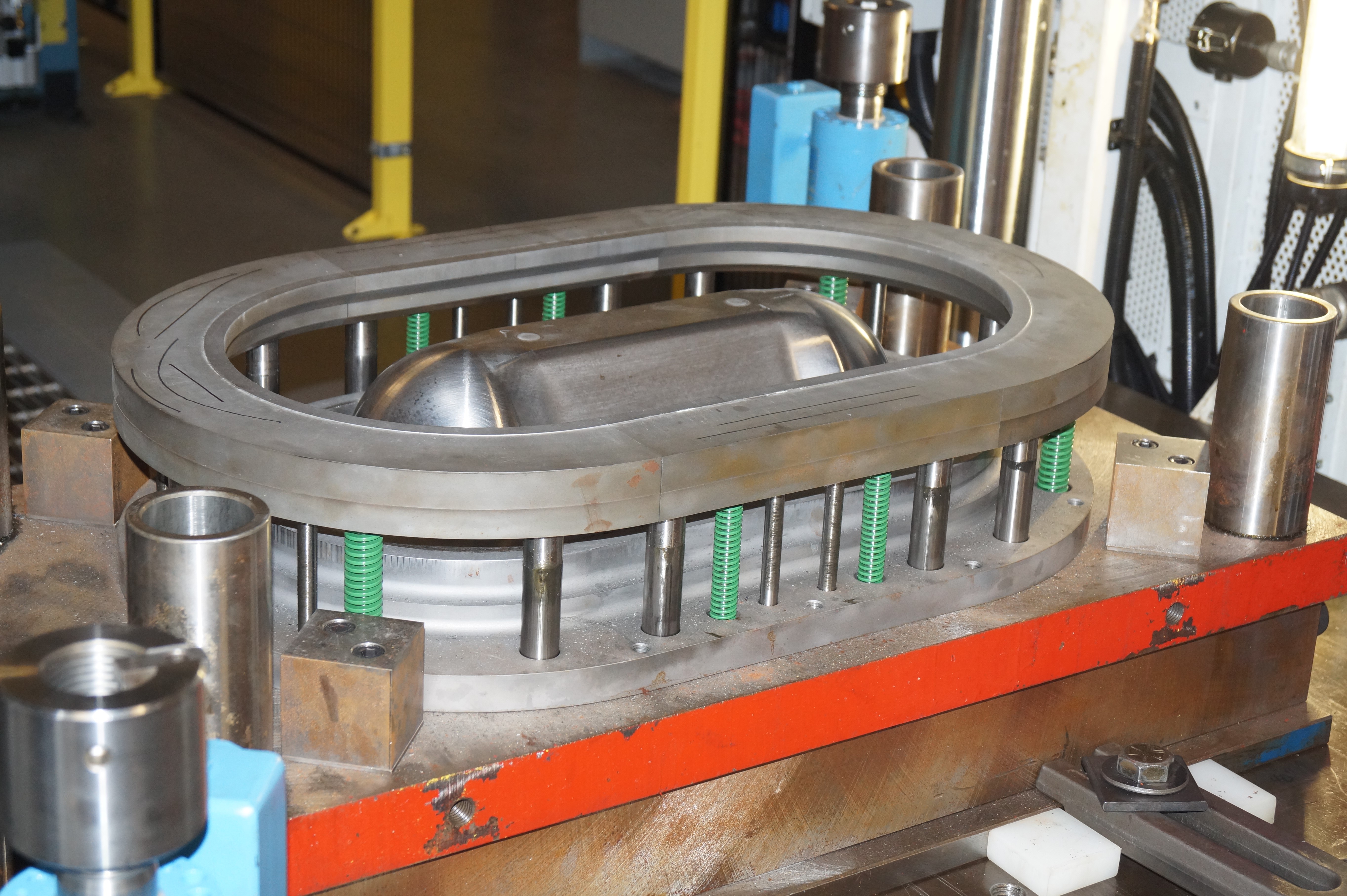
Woven carbon fiber reinforced plastics (CFRPs) are receiving growing attention from the transportation industry because of their high performance to weight ratio [1, 2]. Due to its good geometric conformability, woven CFRP is most suitable for complex part geometries. The highly-automated composite thermoforming process, as shown in Fig 1, was developed to manufacture the defect-free CFRP parts at low cost and cycle time. Material used in the first preforming step is the stacked flat layers of prepregs, which are woven CFRPs impregnated with uncured thermoset resin in desired fiber orientations. These layers are heated above the resin melting temperature to fully soften the prepreg and form into the part shape on a press. The formed part is then cured to harden the resin for the permanent shape [3].
Fig. 1. Schematic of the carbon fiber composite thermoforming process.
In the thermoforming process, most of the part deformation and fiber reinforcement reorientation happens within the preforming step. It is crucial to capture fiber direction at the end of this step with computational simulation for the sake of process optimization. A non-orthogonal model for the woven CFRP preforming process has been developed and incorporated into the LS-DYNA® software as MAT_COMPRF (MAT_293) through the joint effort of this academic and industry team [4].
Constitutive law in the MAT_COMPRF
Woven CFRPs are highly anisotropic in mechanical properties. The prepreg has large tensile modulus along the warp and weft yarn directions because of the stiff carbon fibers and small intra-ply shear modulus, especially at the preforming temperature when the resin is molten as the shear resistance is mostly provided by the resin and the friction between the fiber yarns. To capture this mechanism, MAT_COMPRF fully decouples the tension and shear deformation from small to large shear deformation.
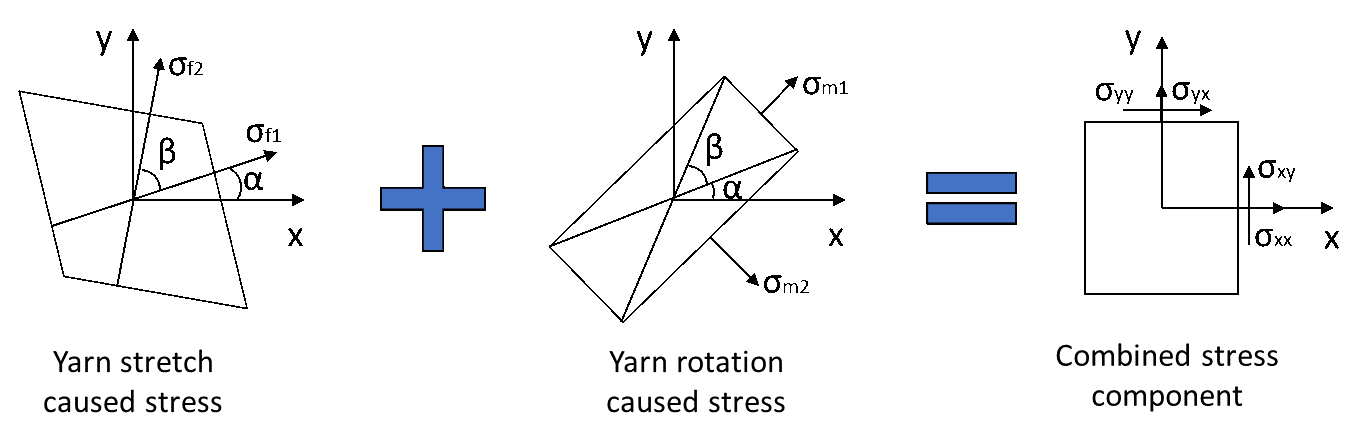
Stress analysis in MAT_COMPRF is shown in Fig. 2. σf1, and σf2 are the stress components caused by yarn stretch, and they are along the warp and weft yarn directions, respectively. σm1 and σm2 are the stress components caused by the yarn rotation. These stress components will be transformed into the local corotational coordinate, summed up as σXX, σXY, and σYY, and will be the stress outputs reported from the material model to the FEM software.
Fig. 2. Stress analysis of the woven CFRP with the modified non-orthogonal model.
The deformation gradient tensor F is utilized in this model to trace the yarn directions and stretch ratios during the preforming via g=F•G, where g and G are the final and initial orientations of the local fibers respectively. It can be used to calculate α, which indicates the relative rotation between the local warp direction and the X-direction in the local corotational coordinate, and yarn angle β, which indicates the amount of shear deformation in the material.
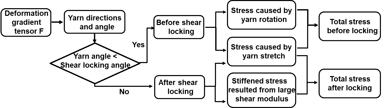
MAT_COMPRF enables users to directly input experimental data to define the stress-strain curves, as well as the shear locking angle, which indicates whether the shear deformation reaches the extent that the rotation resistance between warp and weft yarns is no longer small compared to the tensile modulus of the material. These material properties could be obtained via uniaxial tension, bias-extension, and bending tests in [5]. The flowchart of the model is shown in Fig. 3.
Fig. 3. Calculation flowchart of the LS-DYNA MAT_COMPRF.
In the material subroutine, the warp and weft directions for each element are calculated from the deformation gradient tensor. If the angle between the warp and weft yarns are smaller than the shear locking angle, then the small shear modulus condition will hold. If the angle between the warp and weft yarns reaches to the shear locking angle, the resistance for further shear deformation will greatly increase because the contacted fiber yarns stiffen the woven structure. In this situation, the shear resistance of the model will increase automatically to avoid further large shear deformation.
Experimental validation
The double-dome test, as shown in Fig. 4, was conducted and simulated in LS-DYNA® to demonstrate the capability of the MAT_COMPRF for 3D shape forming regarding different yarn orientations and stacking sequences. The sheet was modeled by reduced integrated shell elements. Each element is about 4 mm × 4 mm with five through-thickness integration points. The punch, binder and die were modeled by rigid shell elements.
Fig. 4. Experimental setup for the double-dome test.
The simulation results in the upper-right quarter of Fig. 5 show that the MAT_COMPRF material model is capable of accurately predicting the physical experiments regarding the yarn angle distribution and blank draw-ins. For instance, the deviation of the maximum draw-in distance is about 7 mm (49 mm in experiment versus 42 mm in simulation). For comparison, an orthotropic material model (MAT_002) is utilized in another simulation whose result is shown in the upper-left quarter of Fig. 5 in the same scale as non-orthogonal model and experiment results. Since the orthotropic model cannot track the material property change during the yarns’ rotation, the corresponding simulation has a maximum draw-in deviation of 24 mm, not capturing the overall process behavior.
Fig. 5. Simulation and experimental results comparison of deformed geometry and yarn angle distribution for double dome preformed part of ±45º single layer woven prepreg.
In the MAT_COMPRF model, the yarn angle is defined as an output variable, while MAT_002 does not have the capability for direct visualization. For clarity, Table 1 compares the resulting shear angles at various locations obtained from the experiment and simulations. Again, it shows that the current model has improved the prediction accuracy.
Table 1. Resulting yarn angles from the single-layer case
Location
A
B
C
D
E
F
Experiment
80º
88º
71º
49º
56º
66º
Sim-orthotropic
70º
85º
86º
47º
59º
77º
Sim-present
81º
88º
73º
46º
60º
70º

Sponsors
This work was supported by the Office of Energy Efficiency and Renewable Energy (EERE), U.S. Department of Energy, under Award Number DE-EE0006867.
References
[1] Teti R. Machining of Composite Materials. CIRP Annals - Manufacturing Technology. 2002;51(2):611-34.
[2] Brinksmeier E, Janssen R. Drilling of Multi-Layer Composite Materials consisting of Carbon Fiber Reinforced Plastics (CFRP), Titanium and Aluminum Alloys. CIRP Annals - Manufacturing Technology. 2002;51(1):87-90.
[3] Yanagimoto J, Ikeuchi K. Sheet forming process of carbon fiber reinforced plastics for lightweight parts. CIRP Annals - Manufacturing Technology. 2012;61(1):247-50.
[4] Zhang W, Ren H, Liang B, Zeng D, Su X, Dahl J, Mirdamadi M, Zhao Q, Cao J. A non-orthogonal material model of woven composites in the preforming process. CIRP Annals. 2017;66(1):257-60.
[5] Zhang W, Ren H, Lu J, Zhang Z, Su L, Wang Q, Zeng D, Su X, Cao J, editors. Experimental methods to characterize the woven composite prepreg behavior during the preforming process. 31st Annual Technical Conference of the American Society for Composites, ASC 2016; 2016: DEStech Publications Inc.