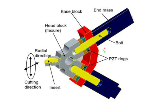
Motivation
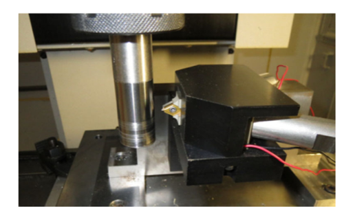
Fig. 1. Model of the resonant-mode elliptical vibration motion generator
Micro-grooving, as a form of surface texturing, has a wide array of industrial applications. However, conventional methods of micro-grooving are plagued by numerous problems including large burrs, big cutting forces, and poor machining quality. To solve these problems, ultrasonic elliptical vibration cutting is used to assist micro-groove turning on cylindrical surfaces. The objective of current research is to predict turning behavior such as the cutting forces in the ultrasonic elliptical vibration assisted micro-groove turning process.
Research Work
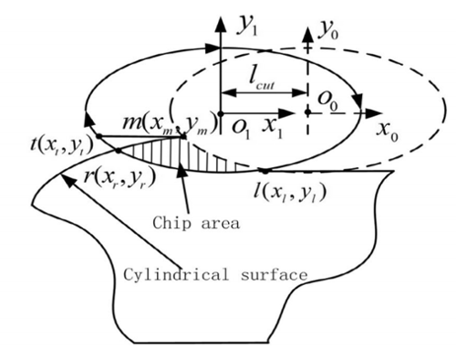
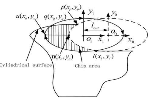
A simplified cutting force analysis model which considers the geometry of the micro-groove features is established by analyzing the cross-sectional area of the cut and the elliptical vibration locus in the ultrasonic elliptical vibration-assisted micro-groove turning process. The removed chip volumes per vibration cycle are calculated by integrating the cross-sectional area of the cut in the elliptical vibration locus direction. The influence of vibration conditions and machining conditions on the removed chip volumes per vibration cycle are analyzed, and a series of micro-groove cutting experiments under different machining conditions are performed to verify the effect by comparing with the variation trend of measured cutting forces in the ultrasonic elliptical vibration-assisted micro-groove turning process.
Fig. 2. Schematic of the ultrasonic elliptical vibration apparatus
NFES must overcome challenges in control, throughput, and repeatability to become a viable manufacturing technique. We have developed an NFES setup to study the physical phenomena involved and to test new control methods. Currently, we are studying the feasibility of electric field modifications to control the fiber deposition process. The electric field modification is achieved by using auxiliary electrodes and modifying the geometries of the electrodes required for NFES. This should allow for tighter resolutions and increased repeatability. A multiphysics model is being developed to aid in the design of the setup. The model will be extended to solve backward control problem, i.e. predict the required parameters for obtaining a desired geometry. Finally, a close loop control system based on machine vision is being developed to improve process reliability.
Fig. 3. Chip cross-sectional area of x-y plane in micro-groove generation
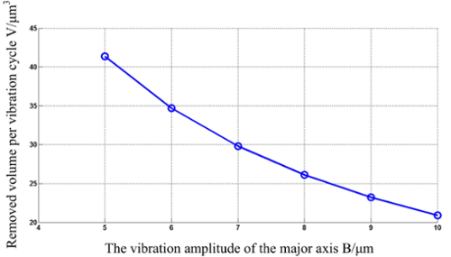
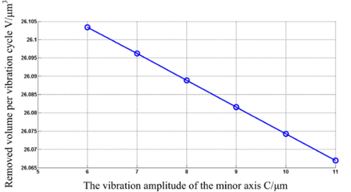
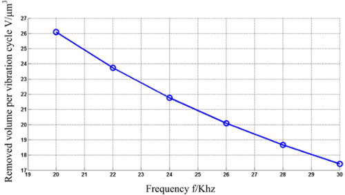
Fig. 4. The influence of vibration conditions on the removed chip volumes. (a) the vibration amplitude of the major axis vs. the removed chip volume, (b) the vibration amplitude of the minor axis vs. the removed chip volume, (c) the frequency vs. the removed chip volume
(a)
(b)
(c)
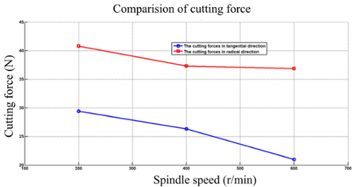
Fig.5. Tangential force and radial force vs. spindle speed at the same depth of cut and feed rate
Sponsor
Results